Benutzer-Werkzeuge
Inhaltsverzeichnis
Skyper
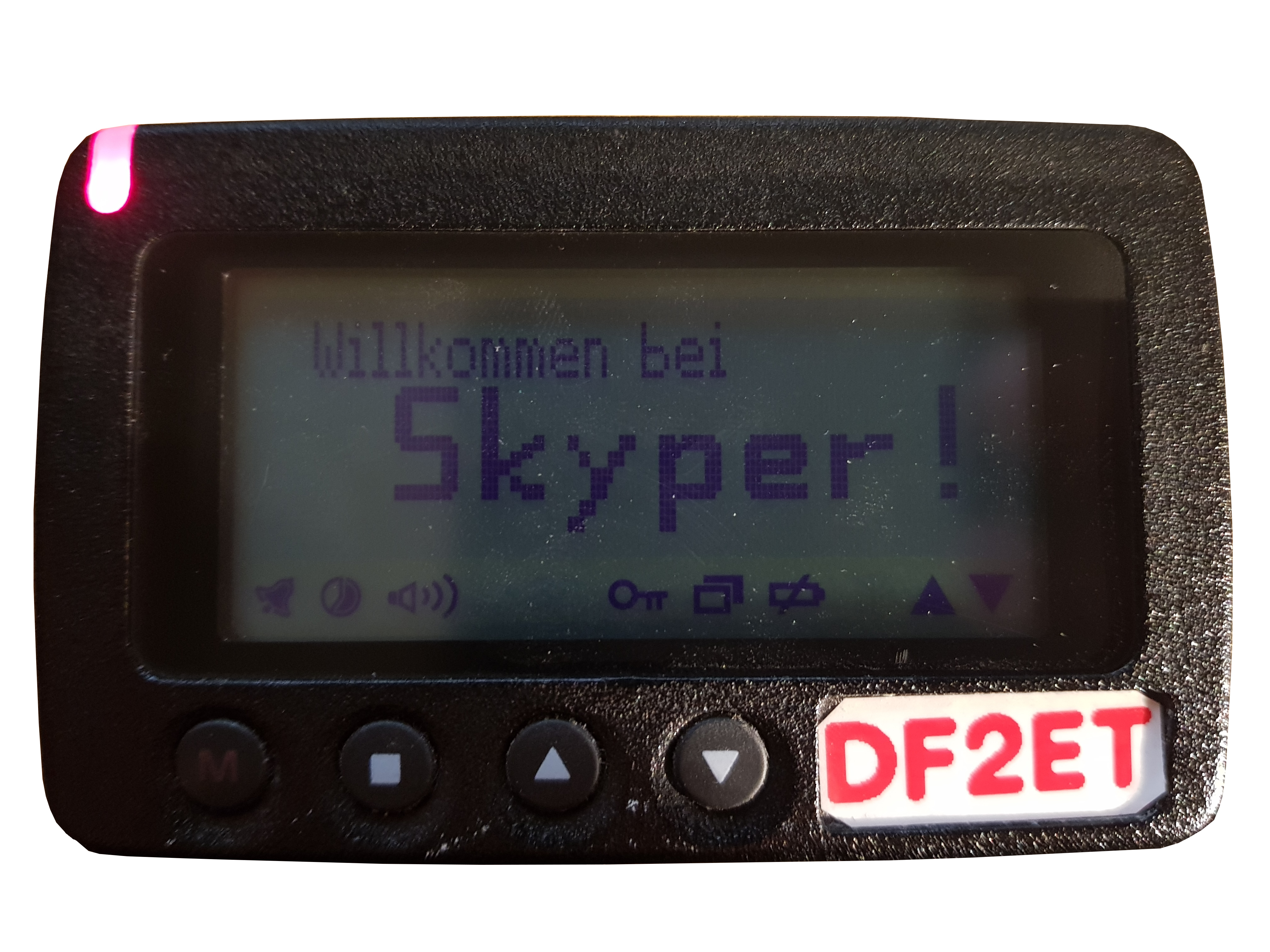
These pagers normally come with a (more or less) hard-coded RIC. It can be found on a small label on the rear side. It is not the „Skyper Nr.“ but the second part of the „ID Nr.“ and consists of seven digits of which the last four are underlined (have been used as a PIN in the commercial Skyper service).
These units support automatic time synchronisation to the DAPNET transmitter/core as well as rubrics messages. The latter need an activation which can be sent out from the hampager portal (see „rubrics“); the activation is stored in non-volatile memory. The rubrics list, the rubrics contents and your individual rubrics subscription however are stored in SRAM and are lost if your battery runs out of power. If this happens, don't worry - the rubrics list is periodically transmitted by the DAPNET core. Just wait until the Skyper has received the list (this may take several hours) and you are able to subscribe to the rubrics again. If you want to avoid this, be sure to replace a weak battery in time.
Skyper versions
There are various versions of Skypers (e.g. Skyper 1, Skyper 2, Skyper 2/A…). The hardware is identical, but they have different firmware features (and bugs…). For example, the Skyper 2 and up versions have auto-repeat/scrolling in the rubrics list and automatic time resynchronization every Sunday morning. They also turn on automatically after inserting a new battery - the Skyper 1 must be turned on by holding the „M“ key. There are a lot more differences between the firmware versions, which are related to closed user groups, overwriting messages etc… DAPNET currently does not use these features, so all Skyper versions are suitable. The hardware modification procedure is always the same.
Modification for UHF ham band use
The old German POCSAG network used 465.310MHz as broadcast frequency. Fortunately the units can be modified to work in UHF ham band range. In Germany there is a centrally coordinated frequency used for POCSAG broadcasting: 439.9875MHz. To make Skypers work on this QRG you need to change the crystal, remove a frontend filter and probably add two capacitors to the replaced crystal. After that it is necessary to re-align the RF components.
Removing the frontend filter
First thing to do is removing the frontend filter because it is designed for the 468MHz range and rather deaf on UHF hamradio band. It has four pins. the outer two are in- and ouput. You can easily remove it by removing solder with solder wick on the outer pins. The inner two are GND and rather hard to get warmed up. Warm those both up at the same time by adding some more solder and then gently pulling the component from the other side.

In order to make it work again you can simply add a little piece of silver wire to reconnect in- and output. A good source is the shortened ands of the crystal which is also exchanged. Of course this is just an easy hack and obviously reduces sensitivity. When re-adding the piece of wire be sure that it is not shortened to GND. It is recommended to add some heat shring tube to isolate.

Exchanging the crystal
Next is to exchange the crystal to get the LO to the correct frequency. You will need a crystal with 69.764583MHz to get the Skyper working on the (German) centralized DAPNET frequency of 439.9875 MHz. To remove the old crystal you can remove solder with a desoldering pump. Be sure not to loose the little SMD resistor between the two pads while heating. It s a 1k2 one just in case you lost it ![]()
The new crystal (from funk24.net for example) should be soldered to the two small holes.

Mounting additional capacitors
To improve the LO you can add two capacitors (15pF and 18pF). The 18pF cap needs to be added on the solder side (bottom) in parallel to a component labelled with „33“. The 15pF capacitor goes to the top side in parallel to the component labelled „R22J“.
There are two ways. You can add standard components which are easier to solder but harder to fit into the case.


An alternative is to use SMD components (for a set see funk24.net). Those are easier to fit into the case but a little more challenging to solder. But there are nice tricks ![]()
The 18pF SMD capacitor on the bottom can be added to two SMD pads which are actually not in use. Those can be found between the „33“ labelled component and a 560R SMD resistor. On the top there are no unused pads apparently. But you can put the 15pf capactor upright between the „R22J“ component and a SMD capacitor next to it. Then solder the two pads to those of the already existing SMD capacitor.


Re-aligning the RF components
After changing the hardware the Skyper needs a realignment to make it work on the new frequency. First step is to realign the LO with the new crystal. You need a transmitter on the new working frequency (439.9875 MHz) transmitting a 600Hz tone to trigger the Skyper. An easy way is to use the test function of UniPager (connected to a RasPager board). This is an overview of pins and trimmers used for alignment:

Then you have to dig onto pin 16 of the receiver IC with a scope. You should see a more or less symmetrical signal. The goal is to align it to be symmetrical calibrating it with trimmer CT2. It should look like this when finished:

When this is finished you can improve reception by tuning the antenna circuit to maximum signal strength. Therefore conncect your scope to pin 12 and tune to maximum signal by turning trimmer CT1 carefully.
If all is done your Skyper should receive messages from DAPNET network. You can test that using the „Send Message“ function of UniPager which circumvents the DAPNET connection and sends out POCSAG calls directly.
RIC programming
Although Skypers come with pre-programmed RIC these can be modified. You will need a hardware interface for RS-232 port and the corresponding (DOS) software.
Hardware
You need an interface that supplies 3v0 to the pager to activate its programming mode. A small SMD PCB that fits into a DB9 connector case is described here: https://github.com/dk4pa/SKYPER_PROGRAMMER. Power is drawn from a USB port and converted to 3v0. A small amount of PCBs is available at cost from the authors. Please contact DK4PA or DF2ET. The Skyper has a programming interface which is located inside the battery compartment. It requires the wiring of GND, 3v0 as well as RX/TX lines. All experiments to build some sort of plug failed so far. Thus we normally solder the 4 wires to the pads after opening the case.

The connection between programming interface mentioned above and Skyper are as follows:

Software
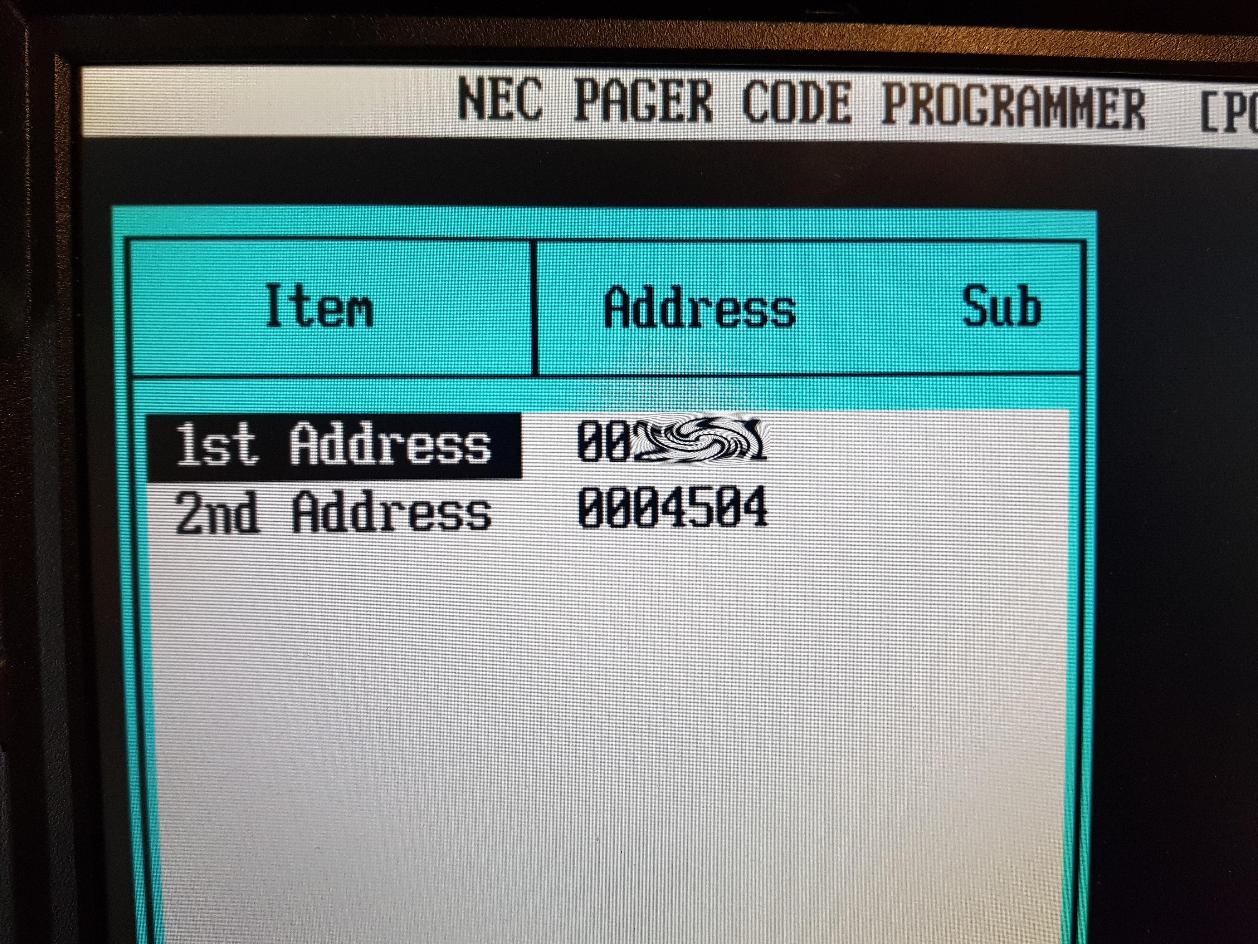
There is a DOS software that is able to read/program Skypers model 1 and 2. The software to use can be found on the internet from various Russian? sources. It refers to the pager as NEC21a which is probably some vode or development name for the units. You will need an (old) MS-DOS machine with a physical serial RS232 interface to run the application. Tests with VMs failed so far.
After starting the software you have to load a .ROM file before you can read the pager configuration. There a different ones corresponding to the Skyper versions 1 and 2. After you have successfully read the pager configuration you can identify its RIC (if the label is lost for example) or even change it to a different value. You will also find the RIC that is used for group calls and rubrics.
Removing the display from the case
The display is mounted in the case with clips. You can use a small screwdriver to *carefully* pull away the case from the display and lift the display (each side after each other)


Photos courtesy DK7TD
Preset of display contrast
Have you ever asked yourself what this tiny trimpot on the rear side of the display board does?
Well if your display is working fine and contrast setting can be done via setup menu there is probably no need to.
The initial setting was done by the manufacturer and normally this should work all right.
In case you have trouble with your display contrast it may be helpful to check this alignment according to the picture shown below.
Turning this trimpot clockwise will increase display contrast while turning counterclockwise will decrease it. Please be aware that this is a very coarse setting. This SMD-trimpot has no upper or lower limitations. It can be turned around the full 360 deg.
The fine adjustment is done afterwards in the Skyper setup menu using the up and down keys.

Separating the display board from the case
Should you have trouble with the silicone rubber keyboard or with the microswitches underneath you may want to take display board and case of your Skyper apart.
Another reason to do this may be that you want to clean the display and case from the inside or to replace a damaged Skyper case with a better one.

One straightforward way to do this is the one DK7TD describes using a small screwdriver. For an experienced user who knows what he's doing this can be the way to go. But there is some risk in it especially if you are doing this for the first time.
If you are unlucky you may end up with a display where some lines of pixels are missing when you power up your Skyper afterwards.
What has happened? Please keep in mind that Skyper hardware is around 20 years old stuff.
While pulling out the display board this way the flexible board connector atop of the LCD display may move and some pins can get loose.
Should this ever happen there is no known way to fix it.

After experiencing this twice up to now (I have modified >20 Skyper) I asked myself:
Is there a safer way to work on the display board?
YES there is one.
You can fix the LCD to the display board applying a few drops of 2K glue at the positions shown below.
After hardening for some hours you can pull out the board using a simple smartphone opening tool at the two shown positions.
One tool is enough - you don't need two of them.


If you did the soldering and the modification on the RF board of your Skyper yourself it should be no problem for you to get the old microswitches out and new ones in.
For me it was difficult to get them here in Germany. The dimensions are listed below.
I found them on eBay. They are quite inexpensive even if you have to order 100 pcs in China.
In my opinion its a good idea to replace all 4 microswitches even if only one is faulty. So the look and feel is the same on all 4 keys afterwards.


X-Ray image of a Skyper 2

Image curtesy of the telegram user „Uran“
Used time zone
The skyper gets its time settings „over the air“. Time is broadcasted via RIC 2504 (hard encoded) and in DAPNET UTC is used (and cannot be changed in the skyper itself).
Seiten-Werkzeuge
