Benutzer-Werkzeuge
Inhaltsverzeichnis
Modification of Ericsson C9000
Background
Einleitung
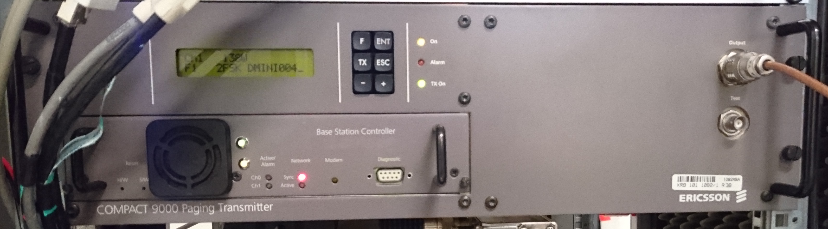
Die Ericsson C9000 Paging Sender wurden in den 90er Jahren bis ca. 2002 an über 200 Standorten für Amateurfunk umgebaut. Nötig war neben einer Zusatzplatine, welche die nicht angeschlossene Endstufe simulierte, eine Schaltung, um die POSAG Signal zu erzeugen. Dazu gab es zunächst die RPC Karte (ein Europakarten großer Rechner mit diskreter CPU, RAM, ROM, EEPROM usw.) Der AATiS e.V. hat dann eine Variante herausgebracht, die auf einem mittlerweile nicht mehr verfügbaren Mikrocontroller basierte. Der Anschluss an das Verwaltungsnetz basierte auf der KISS-Schnittstelle und AX.25.
Beweggründe für die Entwicklung
Weder die RPC-Karte noch die AATiS Platinen sind noch beschaffbar. Da wir noch unumgebaute Ericsson C9000 hatten, wurde kurzerhand die Hardware des RasPagers modifiziert, um mit dem C9000 kompatibel zu sein. Die Entwicklung stützt sich auf http://akafunk.faveve.uni-stuttgart.de/pocsag/.
Grundlegende Beschreibung
Die Software UniPager erzeugt die encodierten POCSAG Signale und sendet sie über die Onboard UART eines Raspberry Pi an einen Mikrocontoller ATMega 8. Dieser arbeitet als FIFO und gibt die Daten im festen Takt von 1200 Baud zum C9000 mit der Bezeichnung MDL aus. Auch das zusätzliche Steuersignal MDE wird erzeugt.
Status des Projekts
Die Hardware ist fertig entwickelt, getestet und funktioniert. Es wurden eine Kleinserie von professionellen Platinen bestellt. Diese können zum Selbstkostenpreis erworben werden. Bitte dazu Ralf DH3WR kontaktieren.
Als Software empfehlen wir UniPager.
Necessary Hardware
You need the following hardware to modifiy your C9000:
- A functional C9000 (obvious)
- A Raspberry Pi (we suggest to use a RasPi 3, but also Version 1 and 2 can be used)
- A RaspagerC9000 PCB (contact DH3WR)
- A step-down converter from 24 V C9000 power supply to 5 V for the Raspberry
- A network patch cable with RJ45 connector at least on one side
- A case for the RasPi (at least the bottom part)
- Hot glue gun (or whatever you perfer to mount the RasPi inside the C9000)
- Cables to connect everything
- Optional: Two DS18x20 OneWire temperature sensors
Modification of C9000
24V Power supply
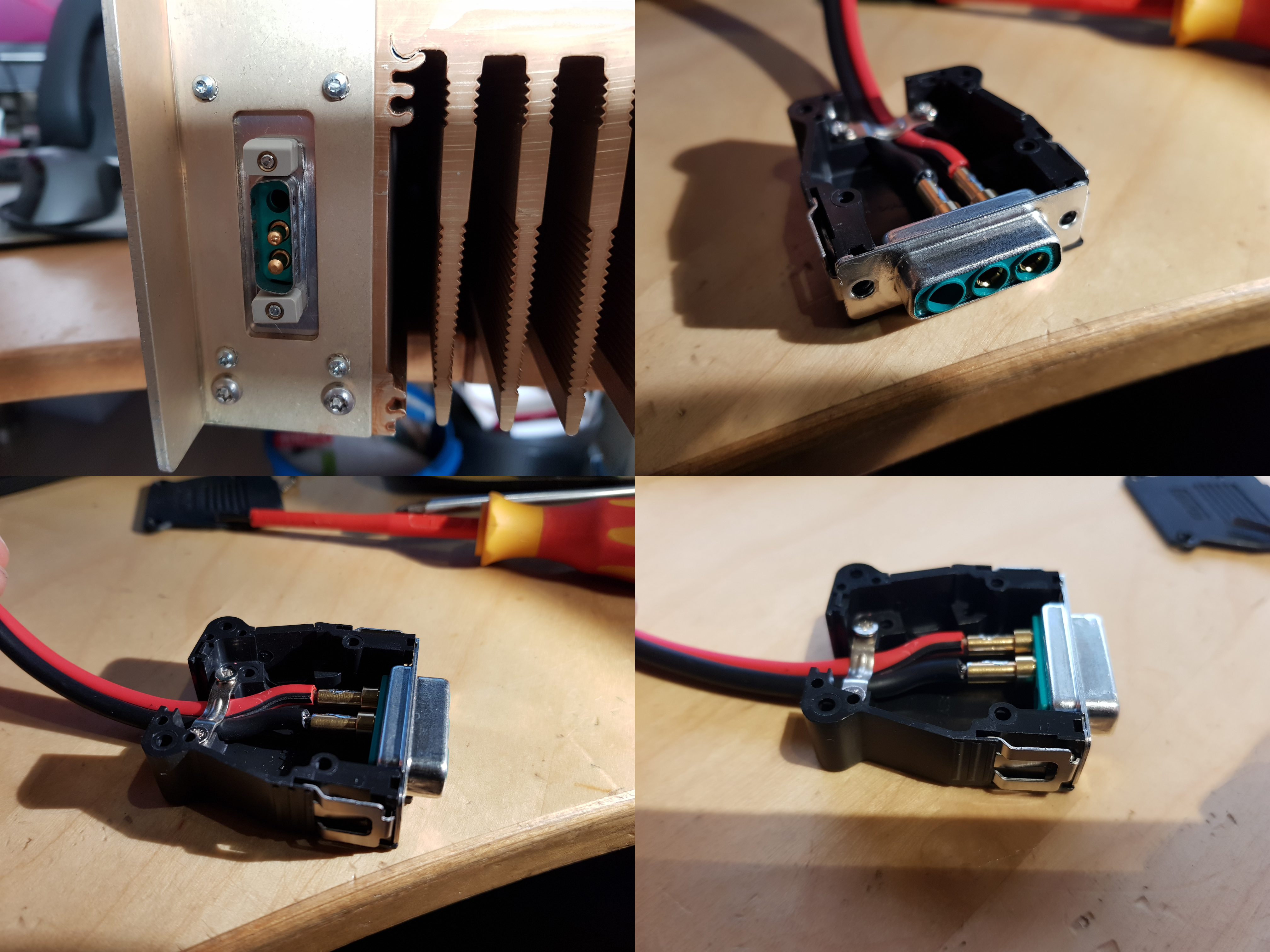
The Compact9000 uses 24V input. At 20W output the unit draws roughly 2.5A at 24V. The power connector is a Sub-D Type with 3 pins. Two of those are used. The center pin is GND (labelled as A2) and the outer pin facing to the bottom (labelled A3) is Vcc. The following parts from Germany electronics distributor Reichelt can be used if the original plug is missing / needs replace:
- 1x MIX-BUG 3W3
- 1x KAPPE 1820
- 2x MIX-BU3 CRIMP
A shopping cart is here: https://www.reichelt.de/my/1503982

Power Supply for Raspberry
There is an internal 5v0 rail but it is unsure if that can supply continous current for running the Raspberry Pi. One solution is to use a DC/DC converter powered by the 24V input. A Mean Well SD-15B-05 is a good choice. The case fits exactly into the small slot aside from the exciter unit. You just have arrange some wires to the backplane of the Base Station Controller board. There are some free pins that can also be used for the ethernet connection of the Raspberry Pi. It can be mounted with two 3mm screws to the side of the case. That should also allow for some heat dissipation.

Using the backplane RJ45 jack for ethernet
There is a RJ45 jack on the backplane of the C9000. It was formerly used to connect a landline telephone connection to the transmitter, so it could make a call if something bad had happend. There is a way to re-use this jack to bring an 100 MBit/s ethernet connection inside the C9000 without mechanical modification of the housing.
Modification of the plugin-PCB
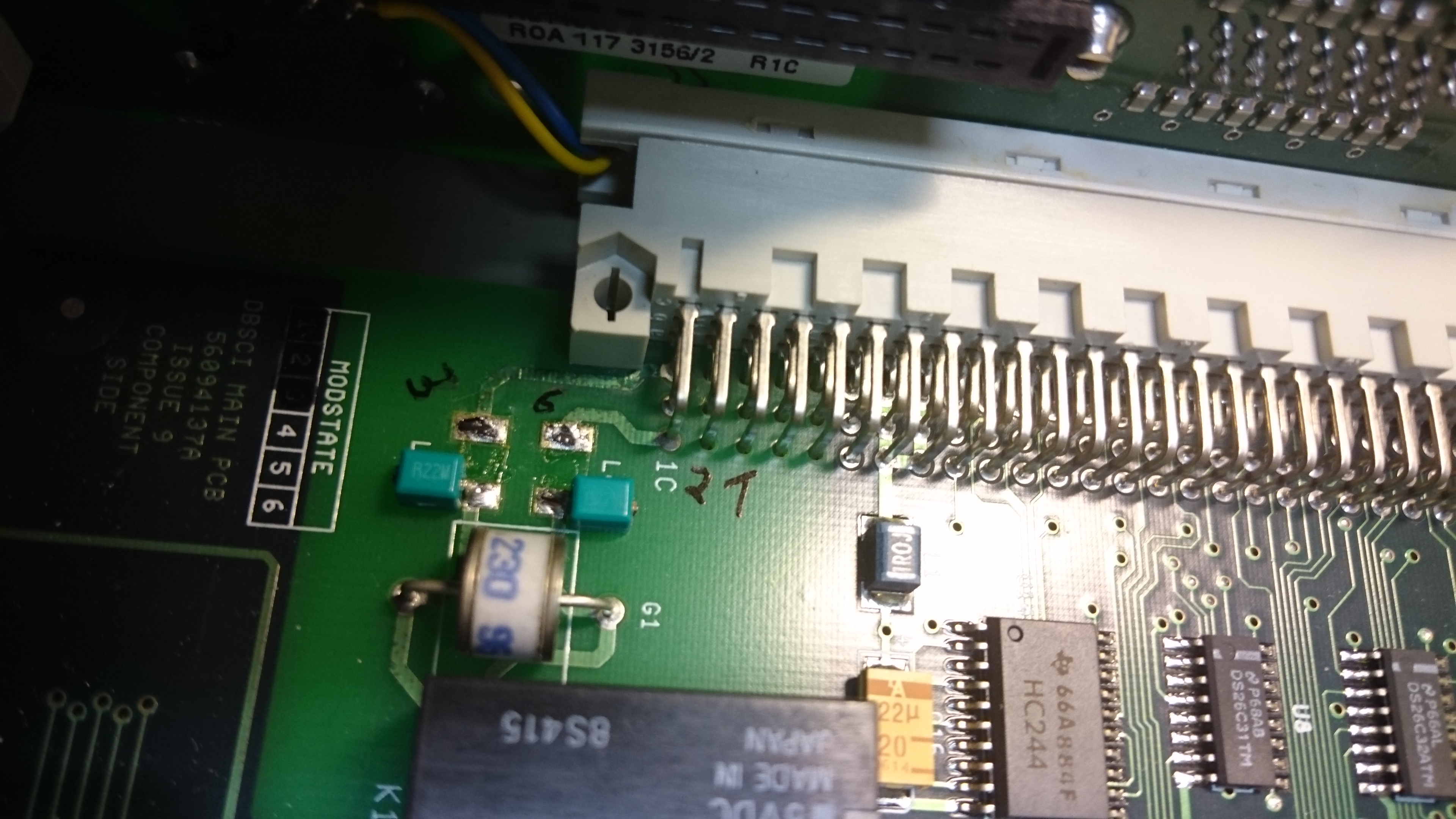
On the backside of the plugin-PCB you will find two multiport connectors. On the left side of the right connector, there is the telephone signal coming in passing through two inductors. As we want you use this pins for ethernet, remove the inductors or „park“ them on the PCB.
Then take a 30 cm long ethernet patch cable whose color you don't like any more and cut of one connector. Keep in mind to leave enough cable so you can connect easily the RasPi which will be hot glued in its bottom housing part to the plugin board afterwards. Solder the important pins on a ethernet cable for 100 MBit/s 1,2,3 and 6 to the PCB pads of the inductors and on the connector pins.
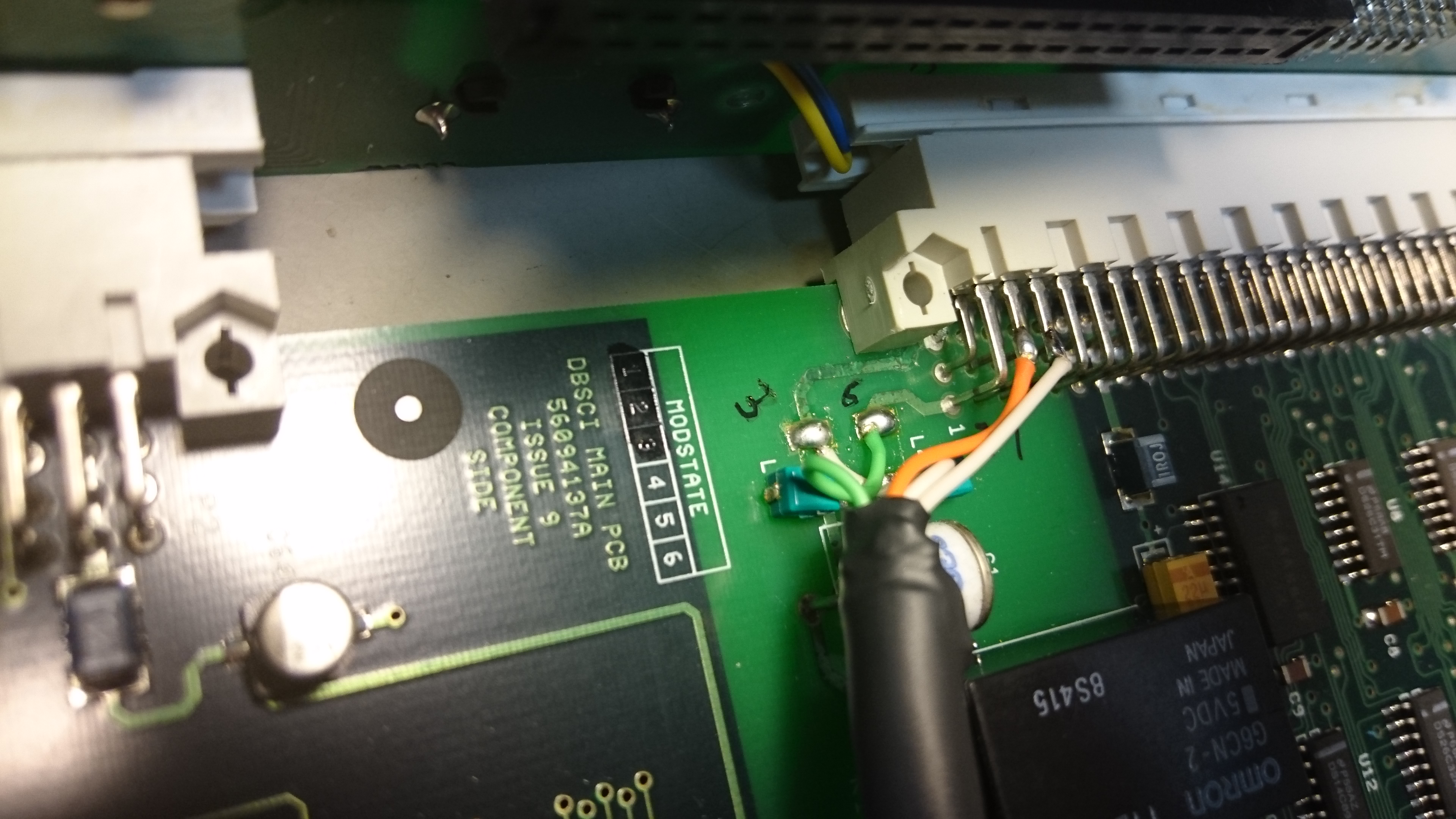 The colors assignments are normally:
| Pin Number | Color |
|---|---|
| 1 | orange/white |
| 2 | orange |
| 3 | green/white |
| 6 | green/ |
This may differ from your patch cable.
Modification of the backplane
As there are only pins 3 and 6 of the RJ45 jack routed on the backplane PCB (remember: former use was landline telephone), you have to connect the pins 1 and 2 by yourselves to the backplace-to-plugin-board connector. Unfortunately, you have to remove and disassemble the backplane completly in order to do so. So take a deep breath and remove all the SUB-D connector threaded sleeves on the backplane. Also remove the four screws holding the backplane and unplug the ribbon cable. Then remove the back plane shield from the backplane PCB.
Solder two wired as indicated on the following pictures:
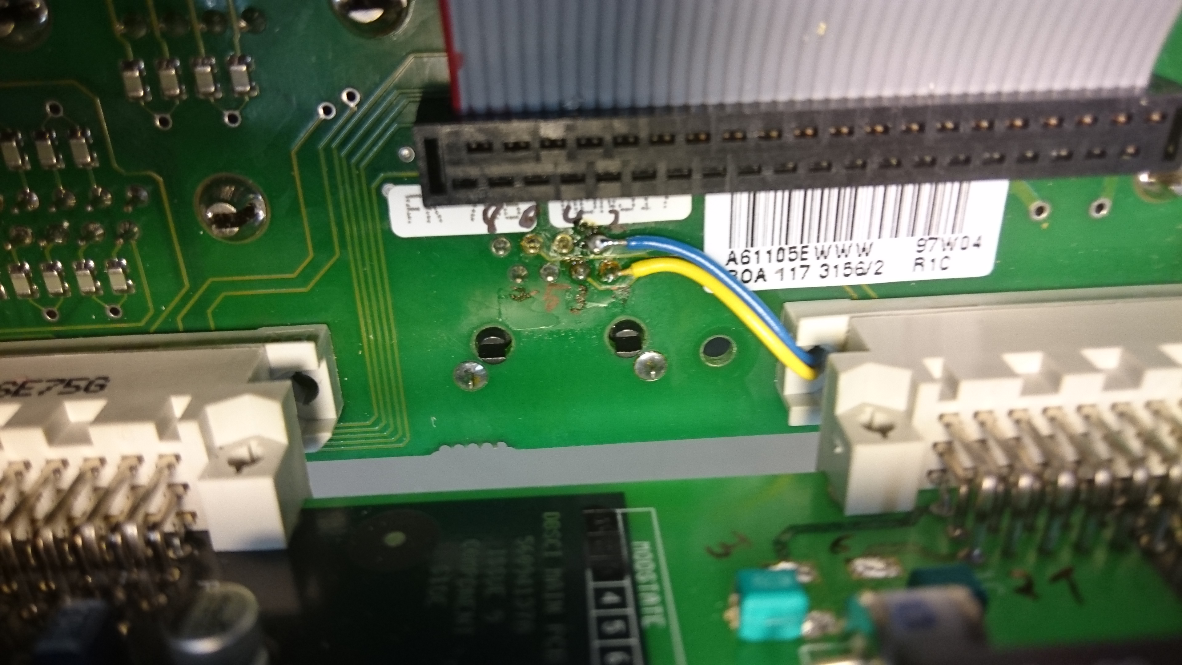
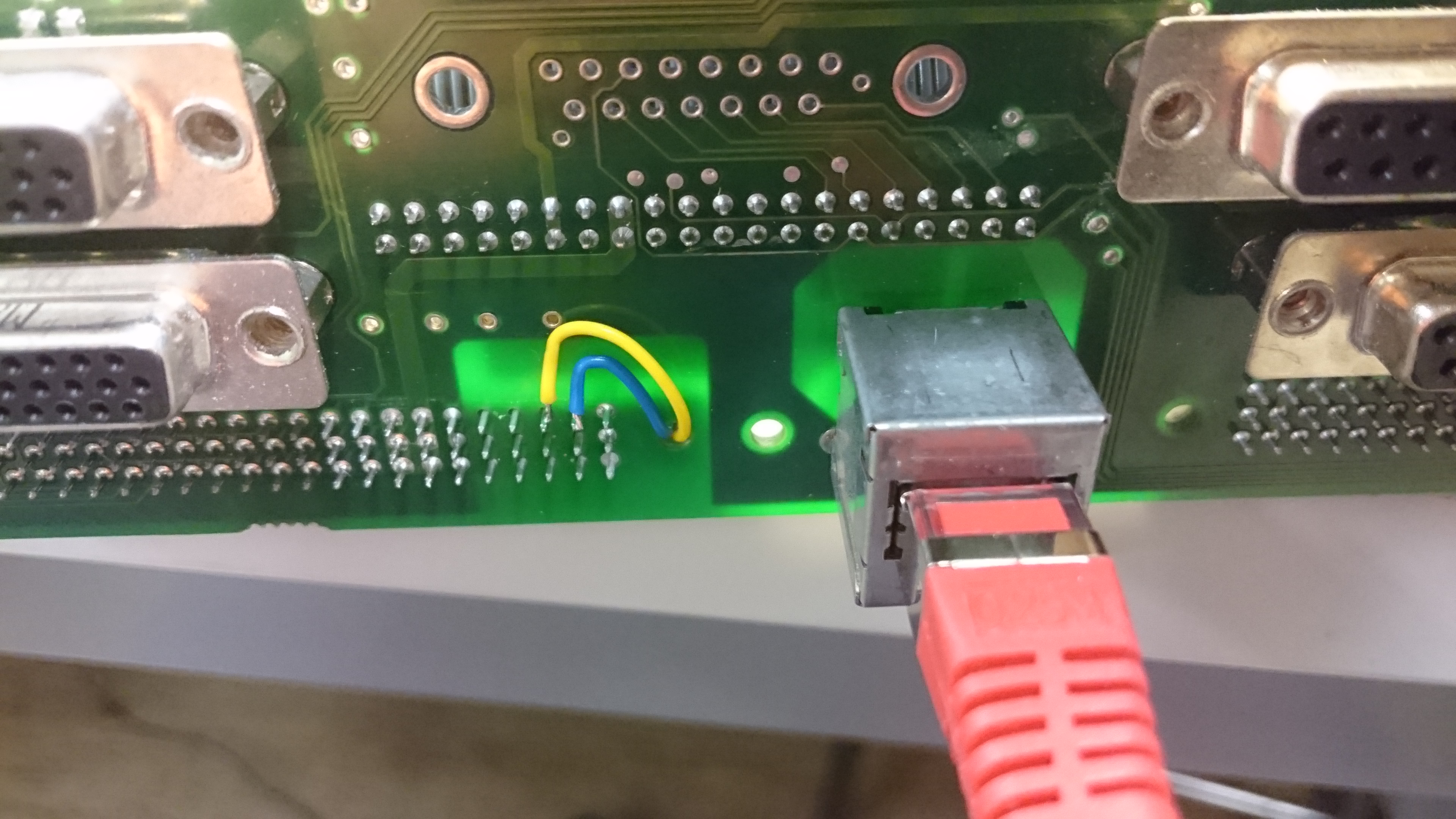
The new cables have to connect from one side of the backplane PCB to its other. Reassemble everything and hope for the best. If you own a network cable tester, it may be a good idea to check the proper connection of the RJ45 jack to the connector of your patch cable, if you just plug the backplane and the plugin board together before you reassemble everything. The line 1,2,3 and 6 must be connected with no shortcut or mix up of the lines.
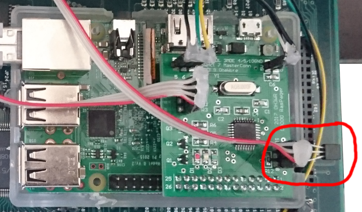
Connection of data signals to C9000
There is a connector on the RasPagerC9000 PCB with pin numbers 1 to 4. This connector is the one to connect the RasPagerC9000 to your C9000.

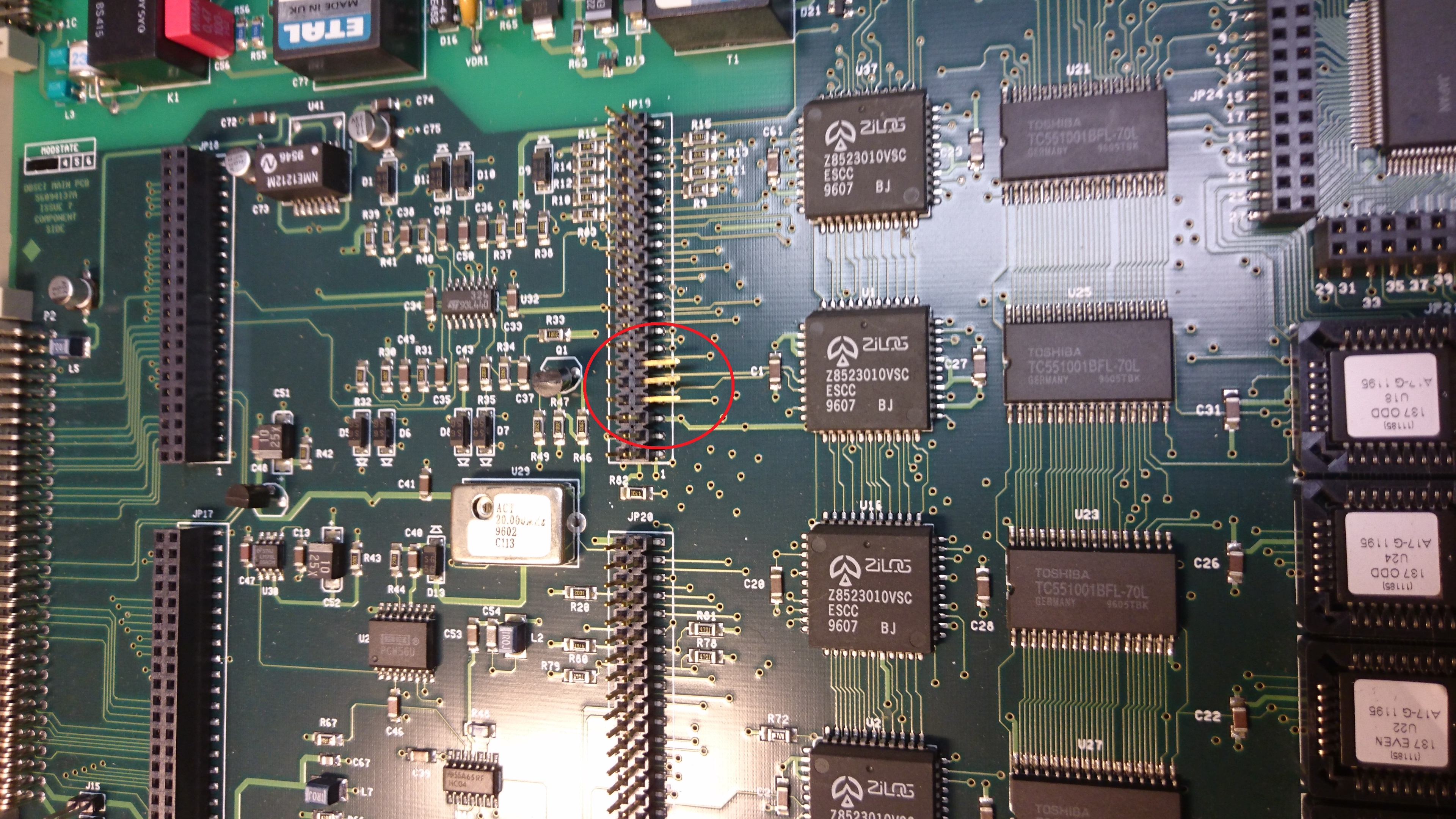
If you have an already modified C9000 with the RCP card formerly used, the 10 kOhm resistor will be already in place. Just add cables from the RasPagerC9000 PCB to the PCB of the personality module and fit it again. Be aware, that not all vias on the personality module are GND, although it might look like this.
Building the RasPagerC9000 PCB
The PCB can be ordered in three different versions:
- Just the PCB
- The PCB with all the necessary parts, but unsoldered
- Soldered an tested PCB
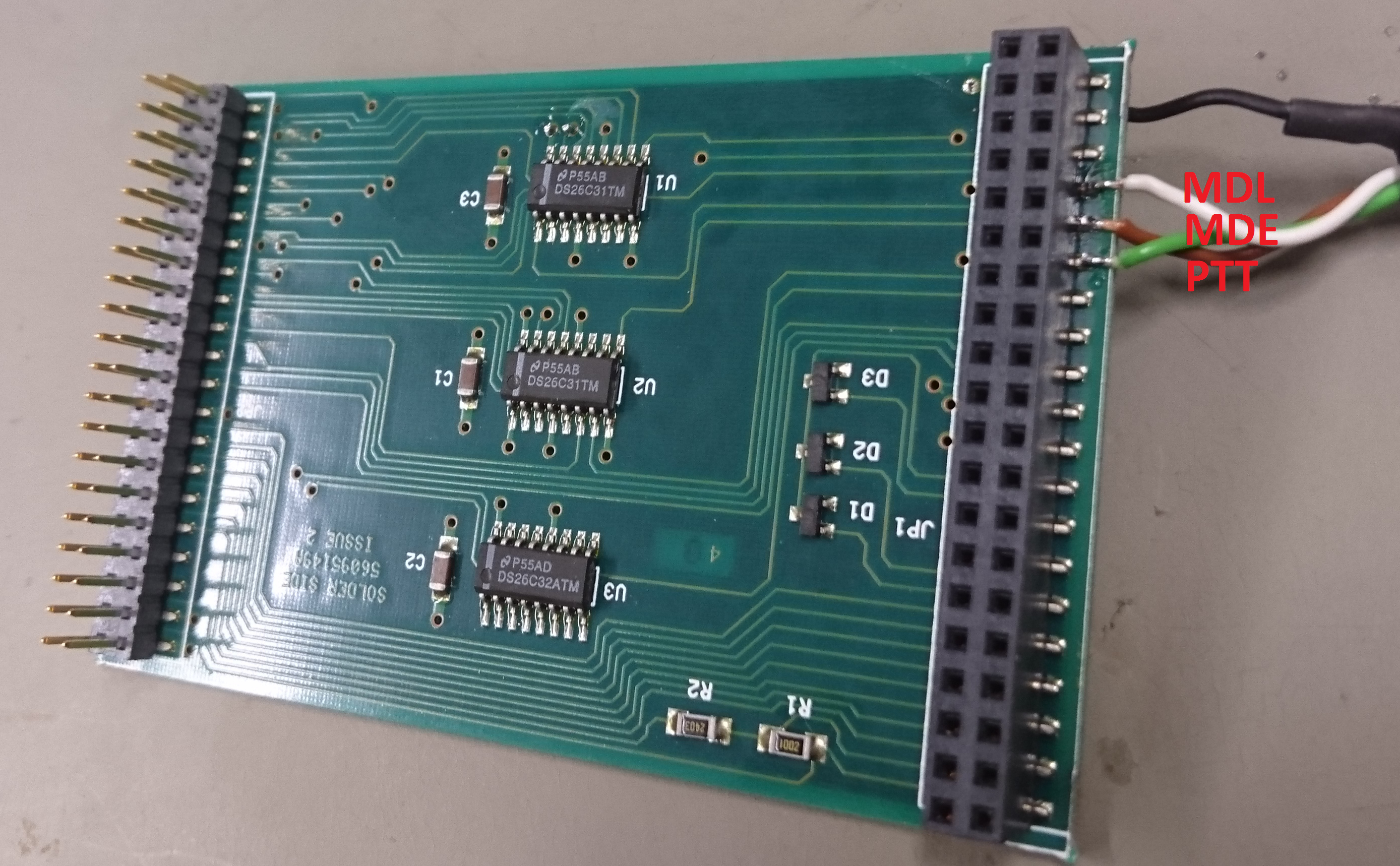
Here are some pictures:


Picture after final integration

Programming the ATMega 8 on the PCB
There is an ATMega 8 on the PCB which has to be programmed before the RasPagerC9000 can work. If is is properly programmed, the green LED will be on if the device is powered on. Fortunately you do not need a separate programmer to get the firmware into the ATMega8. This also applies for possible updates of the firmware. The PCB is designed in a way that you can use the RasPi to program the ATMega8 directly by the RasPi. In order to do so, login to an SSH console on the RasPi and download the github-Repository with the firmware:
git clone https://github.com/rwth-afu/RasPagerC9000.git
cd RasPagerC9000/software/atmega
There is a Makefile available that does all the needed steps for you. Read the programming README to know the commands. Just a hint:
sudo make install_dependencies
make
make fuses
make program
After successful programming of the flash and the fuses, the green LED on the PCB should be on.
Meaning of the LED in the RasPagerC9000 PCB
There are three LEDs on the RasPagerC9000. Their meaning is:
| Color | OFF | ON |
|---|---|---|
| Green | No Power or ATMega8 not programmed | ATMega8 programmed and power on |
| Yellow | No data transfer from RasPi to ATMega8 | Data is received by ATMega8 from RasPi |
| Red | Transmitter is off | Transmitter is on-air |
Software and Software issues
UniPager Software to implement your TX
As stated above, the only existing software for the RasPagerC9000 which is still under support is the UniPager. Have a look here.
Special installation issues for UniPager
 A common pitfall on installing the UniPager is not to read the README of the github repository. As the communication of the RasPagerC9000 ATMega8 and the RasPi is done by the onboard UART interface, the config of the RasPi has to be altered in order to prevent the Linux kernel to send its console messages on the UART.
So first edit /boot/config.txt
sudo nano /boot/config.txt
and add
enable_uart=1
to the file. If you use a Rasberry Pi Version 3, also disable the bluetooth hardware, in order to free the UART interface claimed by the bluetooth chip. Add in a new line
dtoverlay=pi3-disable-bt
Second file to edit is /boot/cmdline.txt. Delete the entry console=ttyAMA0,115200 from the line.
sudo nano /boot/cmdline.txt
After done so, reboot the RasPi. If the ATMega8 is already programmed, the yellow and red LED may not be on or blinking during the boot process. Otherwise, the RasPi is still sending its kernel output to the ATMega which does not make any sense and will prohibit the correct function of the setup.
Front Panel LEDs
You can wire two LEDs to the RasPagerC9000 board that can be integrated into the front panel. The wires need to be connected to pins 5,6,7 of RasPagerC9000. The pinout is as follows:
- Pin 5: GND
- Pin 6: SWAct
- Pin 7: MasterConn

These LEDs indicate if UniPager is connected to the Master (MasterConn) and when its active (SWAct). The corresponding LEDs are not controlled by UniPager directly. You have to use the extra python script called unipagerled.py. It is sufficient to use the preset from the example in the config (/etc/unipagerledconfig.py):
preset = "c9000"
Two resistors (330R) are already present on the PCB (see R10 and R11). The two LEDs can be mounted on the fron panel of the Base Station Controller.

Temperature Monitoring
The RasPagerC9000 PCB is already prepared for easy implementation of a temperature monitoring of the C9000. It is done by cheap DS18x20 OneWire temperature sensors. In order to activate the built-in support for OneWire temperature sensors in the Raspbian software, add the following line tho /boot/config.txt
sudo nano /boot/config.txt
dtoverlay=w1-gpio,gpiopin=18,pullup=on
The DQ-Pin of the OneWire pin assigment is routed to GPIO18.
Reboot your RasPi to activate the changes.
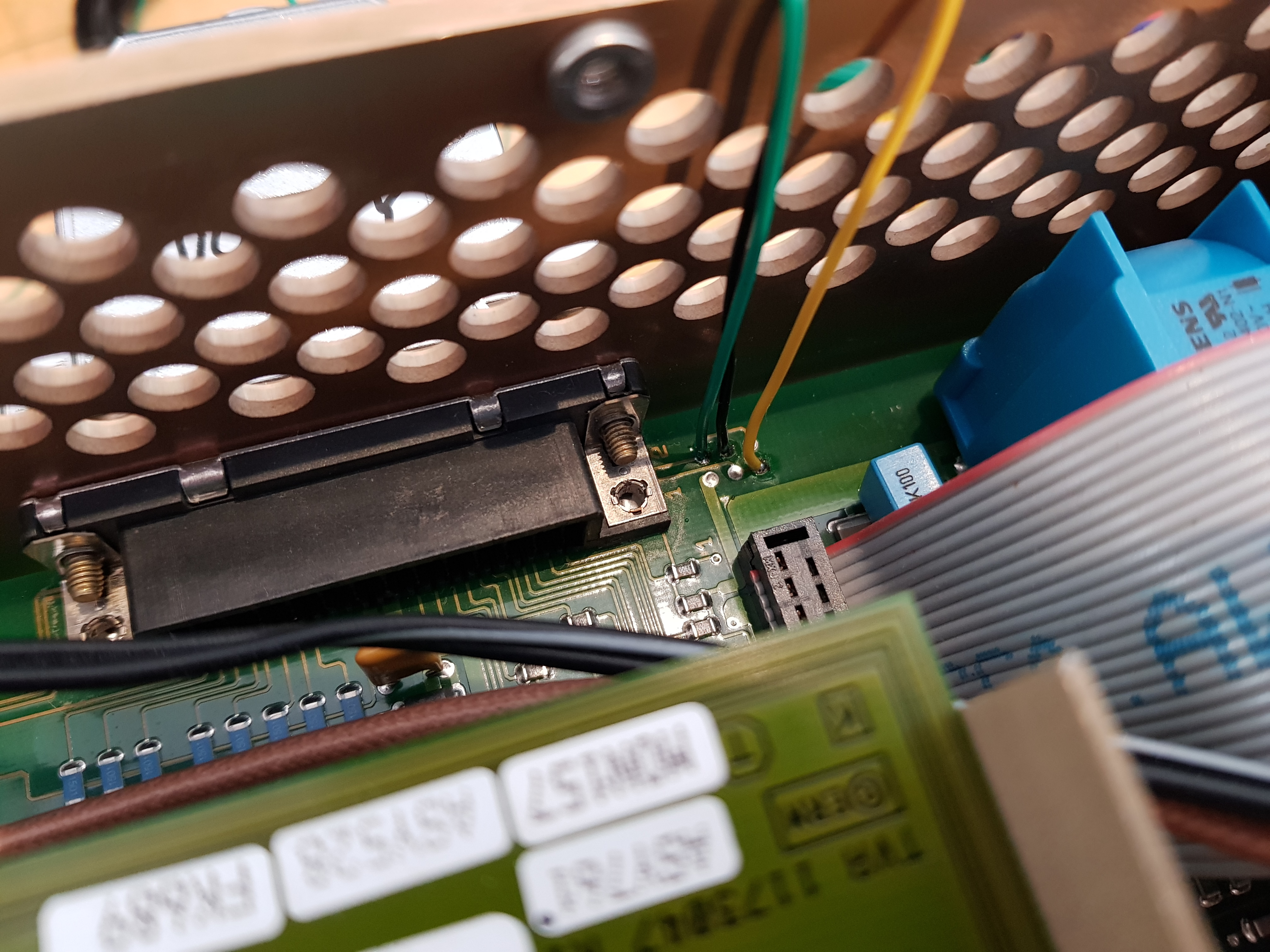
Here a picture of the temperature sensor placed with hot glue next to the PA transistor

A second temperauture sensor the measure the temperature in the inside of the C9000 can be soldered directly on the PCB connector:
Implementation into Munin
Munin is a easily extendable software package to graph values over time. So it is ideal to provide us with temperature-over-time figures based on the measurements of the sensors.
First install a web server on your RasPi to provide access to the figured over http. Respect this order of installing, so the munin installation process will automatically add the apache configuration files for apache.
sudo apt-get install apache2
Install munin and munin-node on your RasPi:
sudo apt-get install munin munin-node
The URL to all your munin graphs is http://YOURIPORDOMAIN/munin.
Munin consists of two parts:
- The
muninwhich gathers information frommunin-nodeswhich can be on other hosts, too. Here we just need the localhost on the RasPi to be fetched. - The
munin-nodewhich is a daemon listening by default on port TCP/4949 for connections, invoking plugins to collect the data and provide it to themunincore.
First adapt the config of the munin:
sudo nano /etc/munin/munin.conf
By default, munin generates all graph images every 5 minuted, independent if someone is looking on them or not. As the write cycles of the SD card in your RasPi are limited, change this to „on-demand-rendering“ by commenting out #graph_strategy cron with a # in front and adding graph_strategy cgi
#graph_strategy cron
graph_strategy cgi
Be aware that you need the cgi modules of apache enabled.
sudo apt-get install libapache2-mod-fcgid
sudo a2enmod rewrite
sudo a2enmod fcgid
sudo service apache2 restart
Change the part where the localhost entry is given a a useful name of your C9000. The example here is c9000.db0sda.hamnet.radio.
# a simple host tree
[c9000.db0sda.hamnet.radio]
    address localhost
    use_node_name yes
A complete example is given here:
# Example configuration file for Munin, generated by 'make build'

# The next three variables specifies where the location of the RRD
# databases, the HTML output, logs and the lock/pid files.  They all
# must be writable by the user running munin-cron.  They are all
# defaulted to the values you see here.
#
#dbdir  /var/lib/munin
#htmldir /var/cache/munin/www
#logdir /var/log/munin
#rundir  /var/run/munin

# Where to look for the HTML templates
#
#tmpldir        /etc/munin/templates

# Where to look for the static www files
#
#staticdir /etc/munin/static

# temporary cgi files are here. note that it has to be writable by
# the cgi user (usually nobody or httpd).
#
# cgitmpdir /var/lib/munin/cgi-tmp

# (Exactly one) directory to include all files from.
includedir /etc/munin/munin-conf.d

# You can choose the time reference for "DERIVE" like graphs, and show
# "per minute", "per hour" values instead of the default "per second"
#
#graph_period second

# Graphics files are generated either via cron or by a CGI process.
# See http://munin-monitoring.org/wiki/CgiHowto2 for more
# documentation.
# Since 2.0, munin-graph has been rewritten to use the cgi code.
# It is single threaded *by design* now.
#
#graph_strategy cron
graph_strategy cgi

# munin-cgi-graph is invoked by the web server up to very many times at the
# same time.  This is not optimal since it results in high CPU and memory
# consumption to the degree that the system can thrash.  Again the default is
# 6.  Most likely the optimal number for max_cgi_graph_jobs is the same as
# max_graph_jobs.
#
#munin_cgi_graph_jobs 6

# If the automatic CGI url is wrong for your system override it here:
#
cgiurl_graph /munin-cgi/munin-cgi-graph

# max_size_x and max_size_y are the max size of images in pixel.
# Default is 4000. Do not make it too large otherwise RRD might use all
# RAM to generate the images.
#
#max_size_x 4000
#max_size_y 4000

# HTML files are normally generated by munin-html, no matter if the
# files are used or not. You can change this to on-demand generation
# by following the instructions in http://munin-monitoring.org/wiki/CgiHowto2
#
# Notes:
# - moving to CGI for HTML means you cannot have graph generated by cron.
# - cgi html has some bugs, mostly you still have to launch munin-html by hand
#
#html_strategy cron

# munin-update runs in parallel.
#
# The default max number of processes is 16, and is probably ok for you.
#
# If set too high, it might hit some process/ram/filedesc limits.
# If set too low, munin-update might take more than 5 min.
#
# If you want munin-update to not be parallel set it to 0.
#
#max_processes 16

# RRD updates are per default, performed directly on the rrd files.
# To reduce IO and enable the use of the rrdcached, uncomment it and set it to
# the location of the socket that rrdcached uses.
#
#rrdcached_socket /var/run/rrdcached.sock

# Drop somejuser@fnord.comm and anotheruser@blibb.comm an email everytime
# something changes (OK -> WARNING, CRITICAL -> OK, etc)
#contact.someuser.command mail -s "Munin notification" somejuser@fnord.comm
#contact.anotheruser.command mail -s "Munin notification" anotheruser@blibb.comm
#
# For those with Nagios, the following might come in handy. In addition,
# the services must be defined in the Nagios server as well.
#contact.nagios.command /usr/bin/send_nsca nagios.host.comm -c /etc/nsca.conf

[c9000.db0sda.hamnet.radio]
    address localhost
    use_node_name yes
Change the munin-node config:
sudo nano /etc/munin/munin-node.conf
Set the hostname to whatever you entered just before:
# Set this if the client doesn't report the correct hostname when
# telnetting to localhost, port 4949
#
host_name c9000.db0sda.hamnet.radio
A complete munin-node.conf would look like:
#
# Example config-file for munin-node
#

log_level 4
log_file /var/log/munin/munin-node.log
pid_file /var/run/munin/munin-node.pid

background 1
setsid 1

user root
group root

# This is the timeout for the whole transaction.
# Units are in sec. Default is 15 min
#
# global_timeout 900

# This is the timeout for each plugin.
# Units are in sec. Default is 1 min
#
# timeout 60

# Regexps for files to ignore
ignore_file [\#~]$
ignore_file DEADJOE$
ignore_file \.bak$
ignore_file %$
ignore_file \.dpkg-(tmp|new|old|dist)$
ignore_file \.rpm(save|new)$
ignore_file \.pod$

# Set this if the client doesn't report the correct hostname when
# telnetting to localhost, port 4949
#
host_name c9000.db0sda.hamnet.radio

# A list of addresses that are allowed to connect.  This must be a
# regular expression, since Net::Server does not understand CIDR-style
# network notation unless the perl module Net::CIDR is installed.  You
# may repeat the allow line as many times as you'd like

allow ^127\.0\.0\.1$
allow ^::1$

# If you have installed the Net::CIDR perl module, you can use one or more
# cidr_allow and cidr_deny address/mask patterns.  A connecting client must
# match any cidr_allow, and not match any cidr_deny.  Note that a netmask
# *must* be provided, even if it's /32
#
# Example:
#
# cidr_allow 127.0.0.1/32
# cidr_allow 192.0.2.0/24
# cidr_deny  192.0.2.42/32

# Which address to bind to;
host *
# host 127.0.0.1

# And which port
port 4949
Store your changes.
We recommend the python plugin for munin to monitor the temperature readings: munin-1wire. As stated in the readme, the pyhton-munin lib is needed, so install it first.
To configure the OneWire IDs and set human readable descriptions, follow the README.md Example:
root@c9000:/etc/munin/plugin-conf.d# cat 1wire
[1wire]
env.alias_000800c34c66 Innenraum
env.alias_000800c312bf PA
Plugins are activated or deactivated by placing a symlink in /etc/munin/plugins to the plugin executable or script. Look here if you need more information on that.
In our case it would be:
ln -s /usr/share/munin/plugins/1wire /etc/munin/plugins/
The result should look like:

The default installation of munin has a lot of overhead which we don't need. So let's clean up a bit:
cd /etc/munin/plugins
ls -l
sudo rm <whatever you don't need>
Restart the munin-node to apply the changes:
sudo service munin-node restart
Also the default apache config allows just accesses from localhost to the /munin URL. Edit
/etc/apache2/conf-enabled/munin.conf and replace
require local
by
require all granted
Restart the apache server to apply the changes.
sudo service apache2 restart
Monitoring with Nagios
It's easy to monitor remote hardware with the nagios nrpe server. It's a local execution agent to run commands on the remote machine and provide the gathered data back to a main nagios instance.
Nagios NRPE Server setup
An example plugin for nagios to check 1Wire temperature sensors is given here:
#!/bin/bash
# Adapted from check_nagios_latency

# Prints usage information
usage() {

if [ -n "$1" ] ; then
echo "Error: $1" 1>&2
fi

echo ""
echo "Usage: check_rasp_temp [-h?] -w warning -c critical"
echo ""
echo " -i 1Wire ID"
echo " -w warning threshold"
echo " -c critical threshold"
echo " -h, -? this help message"
echo ""

exit 3
}

# Checks if a given program is available and executable
check_prog() {

if [ -z "$PROG" ] ; then
PROG='which $1'
fi

if [ -z "$PROG" ] ; then
echo "TEMPERATURE UNKNOWN - cannot find $1"
exit 3
fi

PROG=""
}

# Main
# check progs
check_prog awk
check_prog bc

# process command line options
while getopts "h?i:c:w:" opt; do
case $opt in
i ) ID=$OPTARG; ;;
c ) CRITICAL=$OPTARG; ;;
h | \? ) usage ; exit 3; ;;
w ) WARNING=$OPTARG; ;;

esac
done
shift $(($OPTIND - 1))

# Check options
if [ -z "${WARNING}" ] ; then
usage "No warning threshold specified"
fi
if [ -z "${CRITICAL}" ] ; then
usage "No critical threshold specified"
fi
if [ -z "${ID}" ] ; then
usage "No sensor ID specified"
fi

# Check number formats
if ! echo $WARNING | grep -qE '^[0-9]+(\.[0-9]+)?$' ; then
echo "TEMPERATURE UNKOWN - Wrong number: $WARNING"
exit 3
fi
if ! echo $CRITICAL | grep -qE '^[0-9]+(\.[0-9]+)?$' ; then
echo "TEMPERATURE UNKOWN - Wrong number: $CRITICAL"
exit 3
fi
#if ! echo $ID | grep -qE '^[0-9][a-f]+(\.[0-9][a-f]+)?$' ; then
# echo "TEMPERATURE UNKOWN - Wrong sensor ID: $ID"
# exit 3
#fi

# Perform the checks
TEMP='tail -n 1 /sys/bus/w1/devices/10-$ID/w1_slave | awk -F" " '{ print $10 }' | awk -F"=" '{ print $2 }''
TEMP='bc <<< "scale = 2; $TEMP / 1000"'
PERF="temp=${TEMP};${WARNING};${CRITICAL};;"

COMPARISON='echo "if($TEMP>=$CRITICAL) 1 else 0;" | bc'
if [ $COMPARISON -eq 1 ] ; then
echo "TEMPERATURE CRITICAL: $TEMP | $PERF"
exit 2
fi

COMPARISON='echo "if($TEMP>=$WARNING) 1 else 0;" | bc'
if [ $COMPARISON -eq 1 ] ; then
echo "TEMPERATURE WARNING: $TEMP | $PERF"
exit 1
fi

echo "TEMPERATURE OK: $TEMP | $PERF"
exit 0;
Install nagios nrpe server and the package bc:
sudo apt-get install nagios-nrpe-server bc
and paste the given file into /usr/lib/nagios/plugins/check_1wire. Then make it executable
sudo chmod 755 /usr/lib/nagios/plugins/check_1wire
sudo chown root:root /usr/lib/nagios/plugins/check_1wire
The configure the nrpe commands in /etc/nagios/nrpe.d/1wire_temp.cfg:
command[check_PA_temp]=/usr/lib/nagios/plugins/check_1wire -i 000800c312bf -w 50 -c 60
command[check_C9000_temp]=/usr/lib/nagios/plugins/check_1wire -i 000800c34c66 -w 50 -c 60
The IDs of the sensors after the -i paramter have to be adapted to your lokal used sensors. Check them out with
ls -l /sys/bus/w1/devices/
Also change the 50 and 60 values to your desired warning and critcal temperature level thresholds.
Edit /etc/nagios/nrpe.cfg to allow your nagios main instance to access the nrpe server.
Restart the nrpe server to activate the changes:
sudo service nagios-nrpe-server restart
Nagios Main Instance Setup
On your main nagios instance you create a configuration file with the following content. You also have to have a define host section for your host. Change host_name accordingly.
# Define a service to check the PA Temperature
define service{
        use                             generic-service-rwthafu
        host_name                       c9000.db0sda.hamnet.radio
        service_description             PA Temperature
        check_command                   check_nrpe_1arg!check_PA_temp
        }

# Define a service to check the C9000 Temperature
define service{
        use                             generic-service-rwthafu
        host_name                       c9000.db0sda.hamnet.radio
        service_description             C9000 Temperature
        check_command                   check_nrpe_1arg!check_C9000_temp
        }
The result can look like this:

Replacing the PA-Dummy by open source solution
Introduction
The original PA-Dummies are still available, but setting the emulated output power requires or special mechanical work on the C9000 housing or opening up the C9000. So we looked at the I2C Bus and found out what the C9000 is expecting to think that it's power amplifier is connected and running fine. Further details of the bus communication can be found here.
As a cheap and easy available hareware platform, we chose a Arduino Nano. There are cheap clones on Ebay for less then 1 €/piece.
Drawback and solution
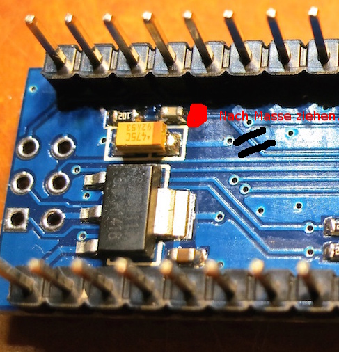
Unfortunately, there is a small modification on the PCB to be done. The reason is, that the C9000 expects always an answer from the emulated I2C Slave. When the UART connection to the USB2Serial chip is opened by the unipager software (or any other software), the CH340 USB-converter resets the ATMega onboard. This is needed for the programming via the bootloader via USB. But due to the reset, the ATMega does not answer the C9000 in that period of time and the C9000 goes into alarm mode, until manual measures on the panel are done. So the workaround is to cut the reset trace from the CH340 to the ATMega and solder it to permanently to ground.


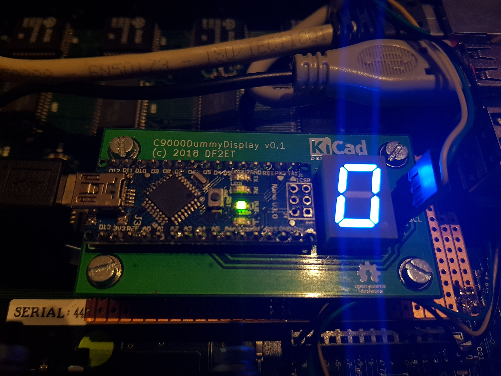
PCB with 7-segement display
There is a PCB that can carry an Arduino nano along with a 7-segement LED to show the configured power level. The sixteen values are shown as a hexadcimal value (0-F). The PCB design is Open Source.
You can find the layout files here:
https://github.com/phl0/C9000PADummyDisplay
The author has some PCBs to sell at cost. Please contact DF2ET if you are interested.
The 7-segement display is supported by the C9000PADummy Arduino code. To activate it you have to compile the code with
#define HAS_7SEG
Programming the flash of the ATMega
To still be able to program the Arduino Nano, you need to connect the ISP Header on it to free GPIO lines on the Raspberry Pi and use avrdude to send the hex file into the flash of the ATMega. In the GitHub-Repo there is an example of a configuration file and a bash script with the necessary parameters for avrdude to work https://github.com/rwth-afu/C9000PADummy/tree/master/software/C9000PADummy.
Connecting to the C9000 I2C Bus
The internal I²C bus can be found on the RCU external bus connector on the back. In addition to that there are some solder pads next to the connector on the inside that you can use to connect the PA dummy to the I²C bus.
There are six solder pads. The pinout is as follows:
             rear panel
  ----------------------------------------------

  ----------------+  SDA GND SDA
  DB25 connector  |   O   O   O
  ----------------+   O   O   O
                     5v0 SCL SCL
So you can either connect a µC based PAdummy (powered from the 5v0 pin) or the Arduino based solution described above (powered by USB from the Raspberry Pi).
Setting the emulated output power
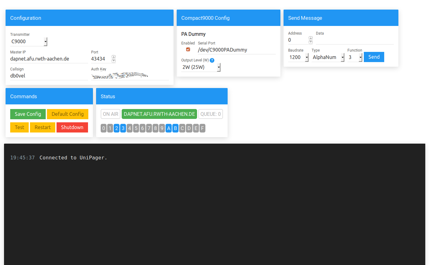
The emulated output power on the Arduino based PADummy can be set from the UniPager web interface. You simply select the desired power level from the drop-down menu. In this case there is an udev rule installed which maps the serial device to a symlink to /dev/C9000PADummy.
After setting the power level you need to adjust the output power of the Ericsson Compact9000 transmitter. Use the menu
Operate -> Tx -> Outp pwr
Adjust the parameter Pset to the power level you set in UniPager. Note that the Pset parameter shows the output power after the (dummy) PA. This corresponds to the power levels shown in brackets in UniPager. The real output power of the C9000 without PA is noted in front of this value.
Seiten-Werkzeuge
